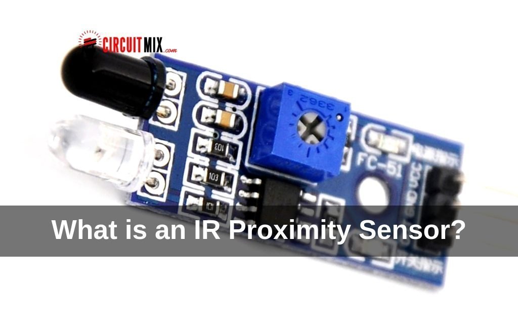
Today we will see what an IR proximity sensor is, what it is used for and how to make one. So let’s begin…
What is a Proximity Sensor?

IR stands for Infrared which is a light with wavelength which is not visible to human eyes but cameras can see it.
It is used in many applications such as TV remote and Night-vision cameras.
In Proximity Sensors an IR LED and a Photodiode is used to find an obstacle. The IR LED emits light in forwarding direction when an obstacle is ahead the light reflects and the Photodiode is activated. By this method, the obstacle is detected.
There are many IR modules available online which are cheap, they cost about $2-3 USD. Which can be used in an obstacle avoiding robot or line follower robot.
In this article, I’m going to show you how to make a simple IR Proximity module which will cost about $1 USD.
Requirements:
- LM358 IC
- Two IR LEDs. (One IR LED and one Photodiode can also be used but as I couldn’t get a photodiode in my local electronic store, I used IR LED.)
- Two white LEDs
- Two 100ohm resistors
- A 15k ohm resistor
- A 10k ohm variable resistor (potentiometer)
- A breadboard and 6v power supply
Connections:

Step by step installation:
- First, insert the IC in the breadboard.
- Next, connect Pin no. 4 of the IC to Ground and Pin no. 8 to +5v.
- Now, connect Pin no. 2 to Ground. (if you need to set the sensitivity of the Receiver then you can add a 10k ohm variable resistor to it. Connect the left terminal to Ground and Right Terminal to +5V and connect the central Terminal to pin no. 2 of the IC, Now you can vary the sensitivity using the variable resistor).
- Now, take the white LED and connect it’s +ve terminal/Anode (longer lead) to pin no. 1 of the IC. and connect a 100/150ohm resistor to the -ve terminal/Cathode (short lead) and connect the other end of the resistor to Ground.
- Next, get the IR LED and connect it’s Anode/+ve terminal to +5v and Cathode/-ve terminal to Ground via a 100/150ohm resistor.
- Now connect the second IR LED in reverse bias. Connect its Cathode/-ve terminal to +5v and connect it’s Anode/+ve terminal to Ground via 15k ohm resistor.
- Once the receiver IR LED is connected, connect a wire from pin no.3 of the IC and Anode of the receiver IR LED.
With this, the connections are done and the Circuit is ready to be powered up by a 6v battery.
When you power up the circuit the LED would be off but as you take your hand over the IR LEDs the white LED should glow.
If it doesn’t then recheck all your connections and try again.
Uses:
The Sensor can be used for many projects. Once completed and tested you can solder it to a PCB and make a small module like the ones sold online.
It can be used for obstacle avoidance robot or line follower robot. Or even for applications like motion detection etc.
Hope this was useful and informative. If you have any questions feel free to ask.
Read more about IR here.
Also, visit our store to get your project tools and components-
