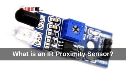
In the previous article, we discussed about IR proximity sensors. How these sensors work and what they are used for.
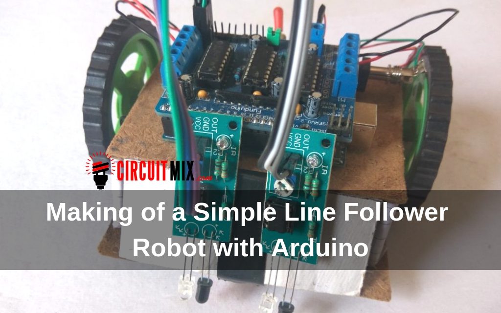
In this article, we will make a simple autonomous line follower robot with Arduino using these sensors. So let’s begin.
What is an Autonomous Robot?
An autonomous robot is simply a machine which is programmed once and then performs tasks on its own.
Basic examples of autonomous robots are-
1. Obstacle Avoidance.
2. Line Follower.
In this article we are going to learn about a simple Line Following Robot which uses Infrared sensors to detect Black line on White surface.
These sensors can be bought online for cheap or you can make them yourself which is even better as it is fun and educational.
Requirements:
- Arduino UNO
- Motor shield
- Geared DC motors with wheels
- IR proximity sensors
- Caster wheel
- Female to Female jumper wires
- DC power jack
- 9 volt batteries with clips
- DPDT switch
- Two wooden or acrylic sheets for chassis
- Spacers
Along with this, you will also need double sided tape, screwdriver, drill (or hand drill) and other basic tools.
Building the Chassis:
First you need to cut the wood into two pieces.
1st one is about 12cm x 10cm.
2nd one is about 10cm x 7cm.
The larger piece is the base where motors will be attached and batteries will be kept. The smaller piece will be used to mount the Arduino and will be placed on top.
Once you have the two pieces according to the measurements, first drill holes in the larger board to attach the angle brackets for motors. Next, connect the motors to the brackets and screw them in place.

Now attach the wheels to them and secure them using some screws.

Now flip the board upside down and stick the caster wheel using double sided tape, or you can drill a hole and connect it using screw.

The lower base is done with this and now we make the upper base to mount the Arduino. For this first place the Arduino on the board and mark the screw holes with a marker. and drill through them. Now, screw down the Arduino in place.

Next, we have to connect the motor shield to the Arduino but before that, we have to solder some pins to the shield.
If you look at the bottom right corner you will see some holes which are the Analog pins next to them is the ground rail and next to it is the +5v rail, solder header pins to all these holes as we will need to connect sensors.

After the soldering is done, we can connect the motor shield on top of Arduino.

Next, we will take some double sided tape and stick it to the bottom of this board and place it on top of the motors, to prevent it from falling you can add some spacers in the front.
Note: As I couldn’t get the spacers of the right height, I used a paper. I first rolled it tightly and they used some super glue to make it stronger. And it works perfectly!

If you are too lazy to build a chassis you can buy one online but making it on your own give you more fun.
Power Supply:
To power our robot we will be using two 9v batteries and use a DBDT switch to turn the circuit on.

Follow the diagram and attach male header pins to one side of the wires or you can leave it as it is. These wires are going to power the motorshild.
Solder a DC power jack to the other two terminals for the Arduino.

NOTE: As here we are using two separate batteries to power the Arduino and Motorshild, we will have to remove the jumper from the Motorshild which is next to the power terminal of the Shield on the right side.

If you don’t do it there is chance that you may damage the Microcontroller.
Refer to the image above to find out the jumper.
Okay, so once we have a power supply unit ready we have to connect the pins to the motorshild and Jack to the Arduino.
(Make sure that you don’t plug in the batteries right now, Cause nothing will work anyway.)
Connect the red (+ve terminal) to the left side of power terminals of motorshild and the Black(-ve terminal) to the right side.
Now find a place around the robot to place the switch, I have placed it behind, near the motors.
Just keep it where it is easily accessible.
Connecting Sensors:
Now we will add sensors to our robot, so it can scan them for the black lines.
These Infrared sensors I’ve used have 3 Pins.

- VCC which is the +ve terminal and should be connected to the +5v.
- GND which is the -ve terminal and must be connected to the ground.
- Signal pin (Out), which is connected to an Analog pin on Arduino.
Here we are using 2 sensors so we will need 2 Analog pins, A4, A5.
Just connect the pins to the Motorshild and place the sensors in the front, one left, one right.
Use a small cardboard piece to mount sensors on.
Connect the sensor’s VCC pin to +5v and GND to GND pin on motor shield.
Connect the Out pin of right sensor to A4 and left to A5.

Coding:
To program the robot first connect the USB cable of Arduino to the port.
Next connect it to your PC. Download the code “Line Follower.ino” and upload it on to the board using Arduino IDE.
Once the code is uploaded the robot is ready to start the action you can now connect the 9v batteries and test.
For the track, use an electric tape that is black and stick it in a circle on a white surface. Now place the robot on the line and switch it On. the bot should start to follow the line if it does not follow the line the you may have to adjust the pot on the module just slowly turn it one side until it turns on then turn it the other side until it is off now it should turn on when on white and off when on black this means the robot is ready to go.

Hope this tutorial was informative and helpful.
If you have any questions fill free to ask in the comments.
