In the previous article I shared some basic information about Arduino. In this tutorial I will be sharing how you can use Bluetooth module with Arduino. This can be used in multiple projects like robotics, home automation, etc. So without wasting any more time, let’s get started.
Requirements:
- Arduino UNO
- Bluetooth Module (I have used AT-09 BLE)
- Breadboard with jumper wires
- LEDs x 2
- 1k ohm resistors x 3
- 2k ohm resistors x 1
- Serial Bluetooth APK
Making The Circuit:

We just have to follow the circuit diagram to make connections.
Refer the steps below for better understanding:
- Place the Bluetooth module on the breadboard.
- We have to divide the voltage from arduino pin because the bluetooth module supports 3.3v. To do this we create a voltage divider using a 2k and 1k ohm resistors. As shown in the image above.
- Make the following connections:
- Vcc -> 5v
- GND -> GND
- TX -> RX
- RX -> TX
- Next connect 2 LEDs on breadboard in series with 1k ohm resistors and connect the anodes to pin no 8 and 9 of arduino.
- After the connection is done, We can move on to write the code to make our setup work.
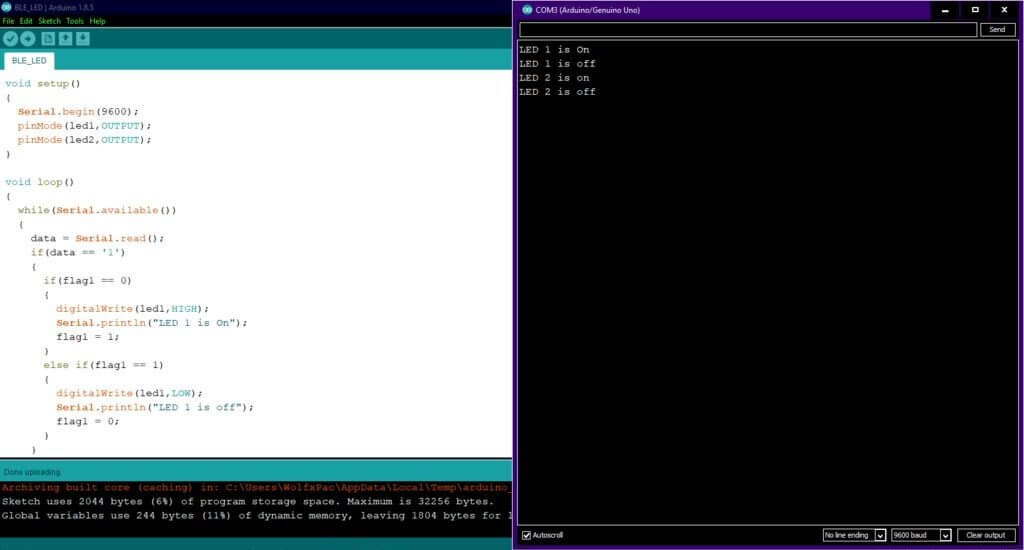
Writing and Uploading Code:
First open Arduino IDE and write the following code, I suggest you write the code and don’t just copy it as it will help you better understand the code.
int led1 = 8; //Set pin 8 as LED1
int led2 = 9; //Set pin 9 as LED2

int data; //Variable to store data

int flag1 = 0; //Variable to store state of LED1
int flag2 = 0; //Variable to store state of LED2

void setup()
{
  Serial.begin(9600); //Enables serial communication
  pinMode(led1, OUTPUT); //Sets LED1 (pin 8) as output
  pinMode(led2,OUTPUT); //Sets LED2 (pin 9) as output
}

void loop()
{
  while(Serial.available()) //While data is being received serially
  {
    data == Serial.read(); //Store the received data in variable
    if(data == '1') //Check if the received data is '1'
    {
      if(flag1 == 0) //Check if the state of LED1 is 0 (off)
      {
        digitalWrite(led1,HIGH); //Turn on LED1
        Serial.println("LED 1 is on"); //Prints message on monitor
        flag1 = 1; //Sets flag1 as 1 (on)
      }
      else if(flag1 == 1) //Check if state og LED1 is 1 (on)
      {
        digitalWrite(led1,LOW); //Turn off LED1
        Serial.println("LED 1 is off"); //Prints message on monitor
        flag1 = 0; //Sets flag1 as 0 (off)
       }
    }
    if (data == '2') //Check if the data is 2
    {
     if(flag2 == 0) //Check if the state of LED2 is 0 (off)
      {
        digitalWrite(led2,HIGH); //Turns LED2 on
        Serial.println("LED 2 is on"); //Print message on monitor
        flag2 = 1; //Sets flag2 as 1 (on)
       }
       else if(flag2 == 1) //Check if state if LED2 is 1 (on)
       {
         digitalWrite(led2, LOW); //Turns LED2 off
         Serial.println("LED 2 is off"); //Prints message on monitor
         flag2 = 0; //Sets flag2 as 0 (off)
        }
      }
    }
 }
Now that the code is ready we can move on to upload it.
- Compiling the code:
After writing the code first save it using ctrl+s and name it something unique like “BLE_test” and compile the code to check for any errors.
- Uploading the code:
First thing to do before uploading the code is to unplug the TX and RX wires. After that you can upload the code. Code will take a few seconds to upload.
- Testing:
Before connecting the wires check if it works as we want. Open the serial monitor (goto tools >> serial monitor) and enter 1 and you will see LED1 turn on, similarly entering 2 will turn on 2nd LED. Entering the same numbers will turn off the LEDs.
Connecting Smartphone:
- To connect phone to Bluetooth module, we need an app. I have used Bluetooth Serial Terminal. Download and install the app on your smartphone with Bluetooth 4.0 or higher.
- Open the app, allow the permission it asks. It should turn on the Bluetooth. Next tap on the connection icon on top right side. It will connect the phone to Bluetooth module.

- After connection is established long press the ‘M1’ to assign it a value. Assign ‘M1’ = 1 and ‘M2’ = 2. These will now act as switches.


- Next power up the arduino via USB. Clicking M1 will turn on LED1 and M2 will turn on LED2. The same buttons will turn off the LEDs.

That’s all for this tutorial. Now you can tinker with the circuit and code to control more LEDs or different devices. In next article we will see how to use this knowledge to build a simple smartphone controlled robot.
Visit our official store: Get a Arduino Mega 2560 R3 Starter Wide Range Kit
Are you are begineer in Arduino? You might like to read Getting Started With Arduino

