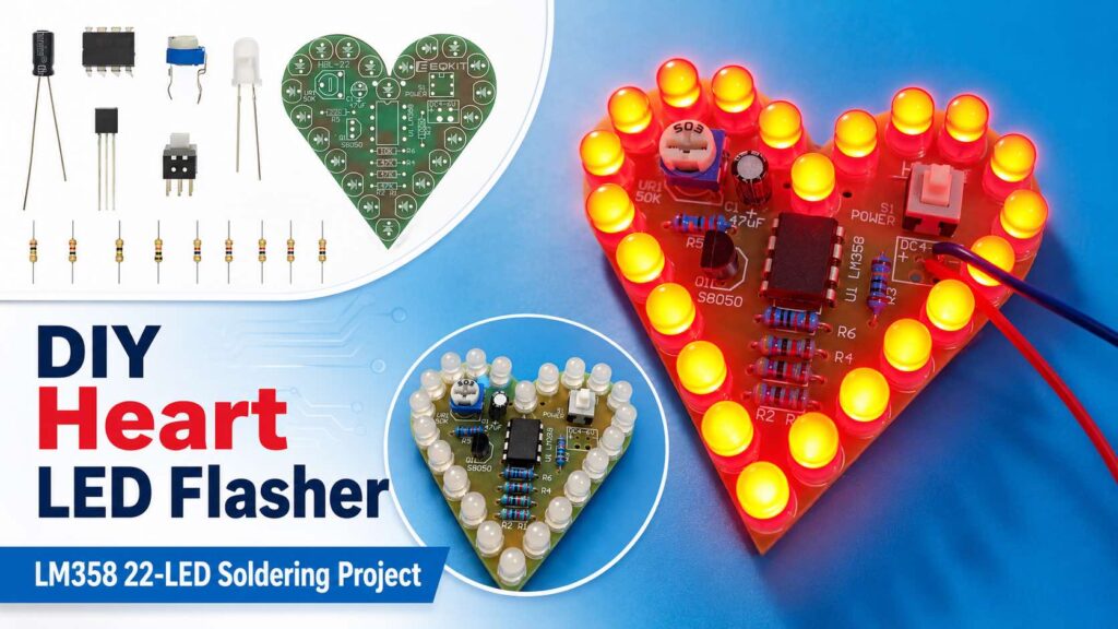
This small heart-shaped LED circuit is a good soldering project for beginners. It uses an LM358 dual op-amp, an S8050 transistor and 22 LEDs to produce an adjustable flashing or fading effect.
The circuit works from 4–6V DC, so a regulated 5V supply or USB power source can be used. The flashing speed can be changed using the small 50k potentiometer fitted on the PCB.
Circuit Diagram
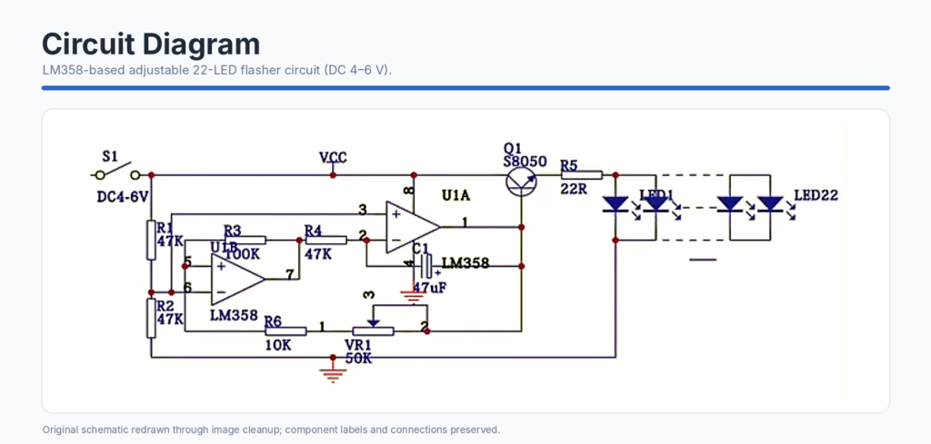
The complete circuit is built around an LM358 dual operational amplifier. Both amplifier sections inside the IC are used to generate the repeating signal required for flashing the LEDs.
Working Principle
The circuit can be understood in five main sections.
1. Power supply
The circuit requires a 4–6V DC supply. Switch S1 turns the circuit on and off.
A regulated 5V supply is recommended. Do not connect the board directly to a 9V or 12V supply because the LEDs and other components may be damaged.
2. Reference voltage
Resistors R1 and R2, both 47kΩ, form a voltage divider. This produces a reference voltage of approximately half the supply voltage.
The LM358 uses this reference voltage while generating the flashing signal.
3. Oscillator circuit
The two operational amplifiers inside the LM358, together with R3, R4, R6, VR1 and C1, form a low-frequency oscillator.
The 47µF capacitor repeatedly charges and discharges. Because of this, the voltage at the output of the LM358 continuously rises and falls.
4. Speed adjustment
The 50kΩ potentiometer VR1 changes the charging and discharging time of the capacitor.
Turning VR1 in one direction makes the LEDs flash faster. Turning it in the opposite direction makes the effect slower.
5. LED driver
The LM358 cannot safely supply the combined current required by all 22 LEDs directly. Therefore, its output controls the S8050 NPN transistor Q1.
The transistor handles the LED current, while R5, the 22Ω resistor, limits the total current flowing through the LED section.
All the LEDs are connected together, so they brighten and dim at the same time rather than working as a chasing-light sequence.
Electronic components
| PCB marking | Component | Value | Quantity |
|---|---|---|---|
| R5 | Resistor | 22Ω | 1 |
| R6 | Resistor | 10kΩ | 1 |
| R1, R2, R4 | Resistor | 47kΩ | 3 |
| R3 | Resistor | 100kΩ | 1 |
| C1 | Electrolytic capacitor | 47µF | 1 |
| VR1 | Potentiometer | 50kΩ | 1 |
| U1 | LM358 dual op-amp | DIP-8 | 1 |
| S1 | Power switch | 6-pin | 1 |
| Q1 | S8050 NPN transistor | TO-92 | 1 |
| LED1–LED22 | LEDs | 5mm | 22 |
Tools used
- Soldering iron
- Solder wire
- Side cutter
- PCB holding stand or helping hands
- Soldering mat
- Multimeter
- Regulated 5V DC supply
How to Assemble the Circuit
The pictures below show the main stages of assembly. Some repeated soldering steps are not shown, but the same method is used for all similar components.
Step 1: Arrange the components
Before starting, place all the components on the workbench and separate them according to their values. Check the resistor values before inserting them. The resistors look similar, so it is better to confirm them using their colour bands or a multimeter.
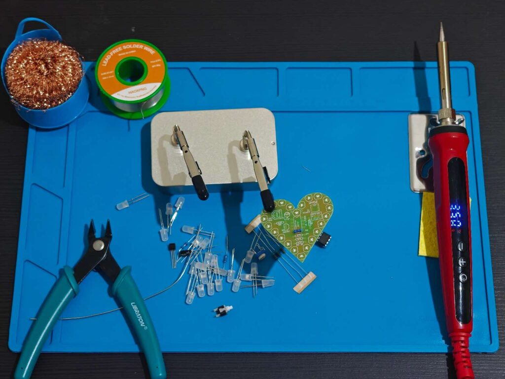
Start with the components having the lowest height. This normally means installing the resistors first.
Step 2: Insert the resistors
Insert the resistors into the positions marked:
- R1, R2 and R4: 47kΩ
- R3: 100kΩ
- R5: 22Ω
- R6: 10kΩ
Resistors do not have polarity, so they can be installed in either direction.
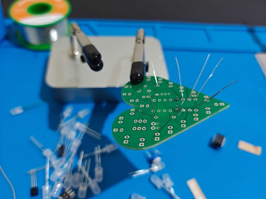
Bend the legs slightly on the back side to stop the components from falling when the PCB is turned over. Do not bend them completely flat because this can make later adjustment difficult.
Solder one leg first, check that the resistor is sitting properly, and then solder the second leg.
Step 3: Install the smaller electronic components
After the resistors, install the following parts:
- 50kΩ potentiometer
- 47µF capacitor
- S8050 transistor
- LM358 IC
- Power switch
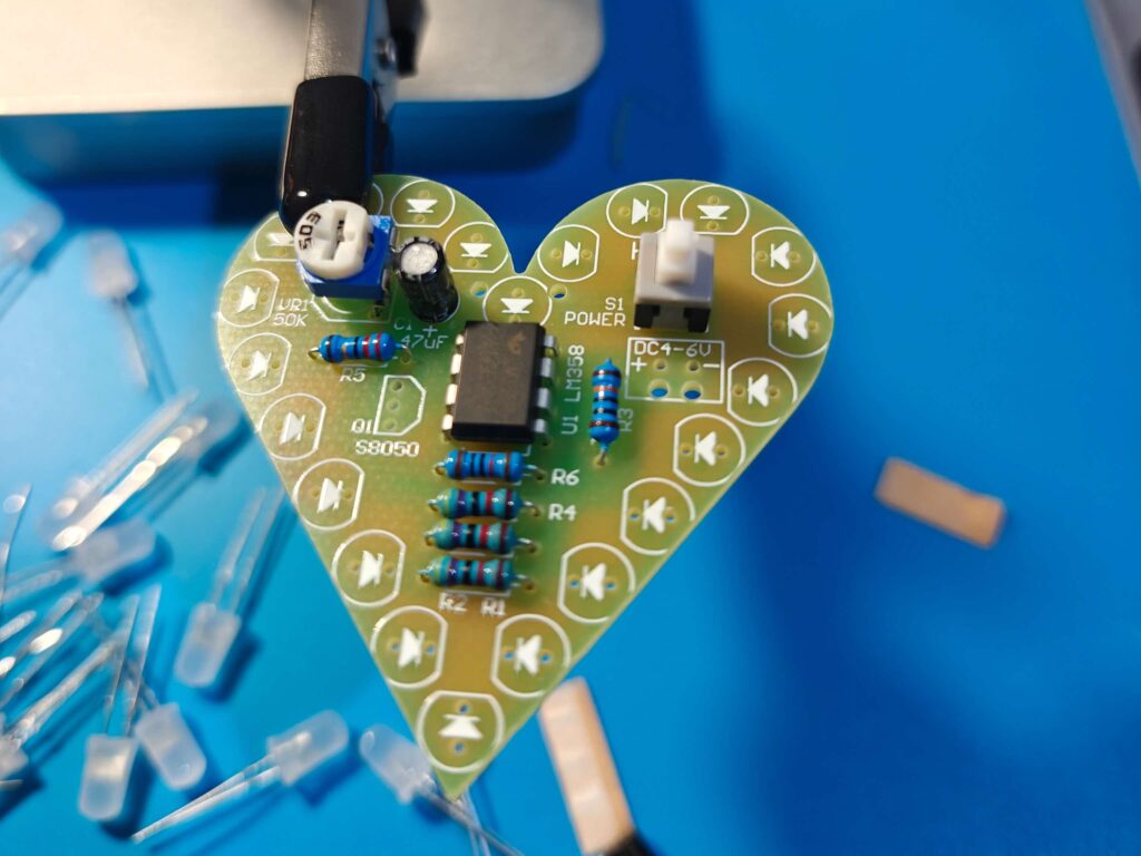
Pay attention to the orientation of the components.
Electrolytic capacitor
The capacitor has polarity.
- The longer leg is positive.
- The side with the stripe is negative.
- Match the positive leg with the “+” marking on the PCB.
S8050 transistor
Match the flat side of the transistor body with the outline printed on the PCB. Do not force the legs into the wrong holes.
LM358 IC
The LM358 has a notch or a small dot showing its orientation. Match this marking with the notch or pin-1 marking printed on the PCB.
Avoid heating the IC pins for too long. A soldering temperature of around 330–350°C is normally suitable for this type of work.
Step 4: Solder and trim the leads
Heat both the PCB pad and the component leg together. After about one second, apply a small amount of solder.
A good solder joint should cover the pad and form a smooth shape around the component leg. Avoid using too much solder because it may join two nearby pads.
After the joints have cooled, cut the extra leads using the side cutter.
Inspect the back side carefully for:
- Unsoldered pins
- Loose joints
- Solder bridges
- Incorrectly placed components
Step 5: Install the LEDs
The LEDs should be installed after most of the smaller components are completed.
LED polarity is important:
- Long leg: anode or positive
- Short leg: cathode or negative
- Flat side of the LED body: cathode
- K marking on the PCB: cathode
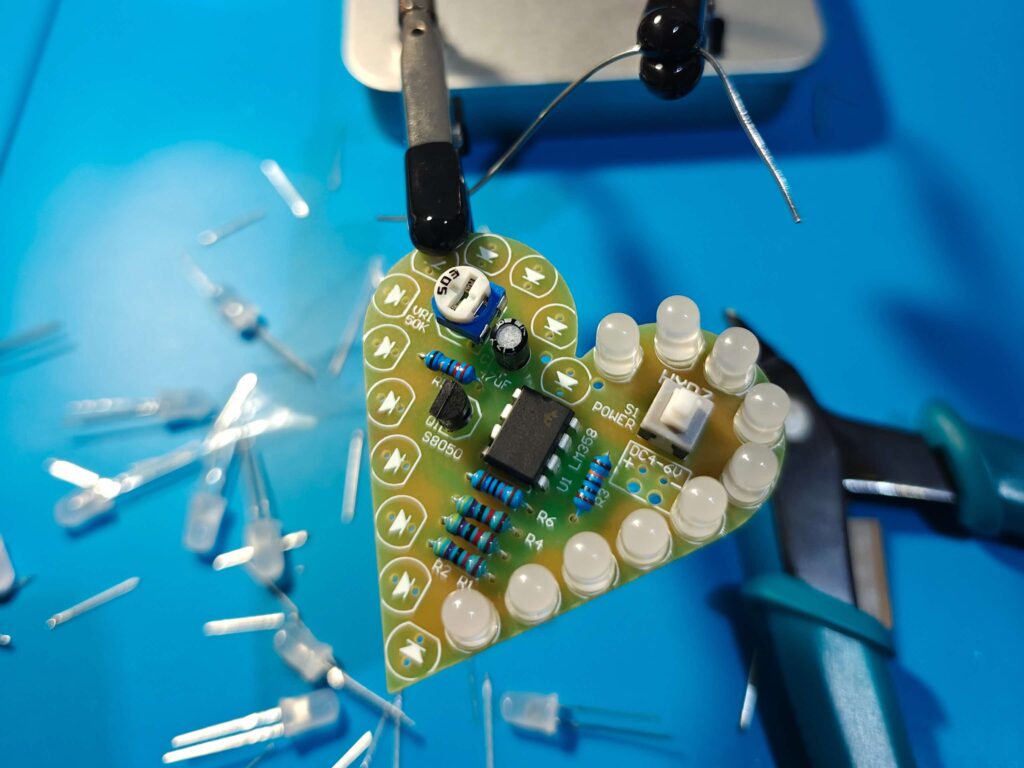
Step 6: Complete the LED ring
Continue fitting the remaining LEDs around the edge of the heart-shaped PCB. Keep the LED bodies at approximately the same height. This gives the finished project a much cleaner appearance.
After soldering all 22 LEDs, cut the extra legs close to the solder joints. Make sure the cut leads do not fall between the PCB tracks and create a short circuit.

Step 7: Check the circuit before powering it
Before connecting power, inspect the PCB once again.
Check that:
- The LM358 is installed in the correct direction.
- The capacitor polarity is correct.
- The S8050 transistor matches the PCB outline.
- All LED cathodes are connected to the holes marked K.
- There are no solder bridges.
- The positive and negative supply wires are connected correctly.
A multimeter in continuity mode can also be used to check that the positive and negative supply terminals are not shorted.
Step 8: Connect the power supply
Connect a 4–6V DC supply to the power input pads.
- Connect positive to the + terminal.
- Connect negative to the − terminal.
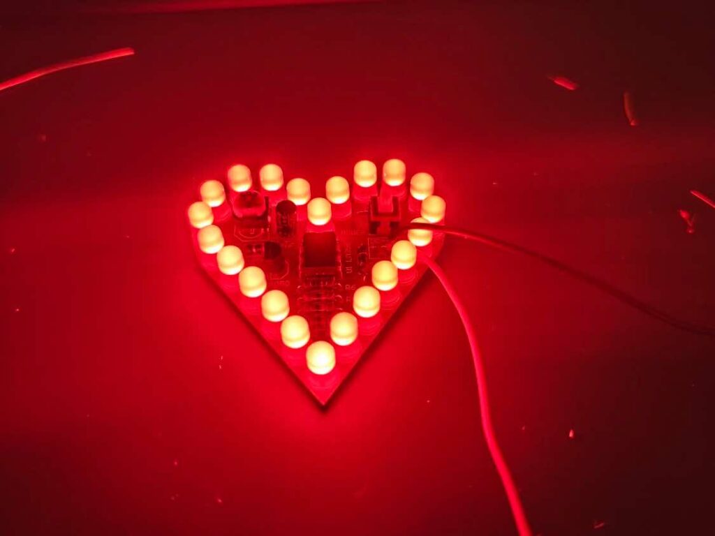
Turn on the power switch. The LEDs should begin flashing or fading together.
Troubleshooting
None of the LEDs are working
Check the supply polarity, power switch, LM358 direction and transistor orientation. Also confirm that the supply voltage is between 4V and 6V.
Only one or two LEDs are not working
The affected LEDs may be installed backwards or may have a poor solder joint. Recheck their polarity and soldering.
LEDs remain continuously on
Check the connections around C1, VR1, R3, R4 and R6. A short circuit or incorrect resistor value in the oscillator section can stop the flashing action.
Flashing speed does not change
Inspect the three pins of VR1. One of its pins may not be properly soldered.
LEDs are not equally aligned
Reheat one LED leg at a time and gently reposition the LED. Avoid pulling it while both joints are solid, as this may damage the PCB pad.
Final Result
This project is simple, but it gives good practice in identifying components, checking polarity, soldering closely spaced pads and aligning multiple LEDs.
The finished heart-shaped light can be powered from a 5V source and used as a small decorative light, beginner soldering project or handmade electronic gift.